6.5 Images from Lenses and Mirrors
10 min read•june 18, 2024
Daniella Garcia-Loos
S
Saarah Hasan
AP Physics 2 🧲
61 resourcesSee Units
Images From Lenses and Mirrors
Let’s talk about mirrors, optical devices that form images by reflecting light. We’ve all looked into a mirror and seen images of our faces and nearby objects; in this section, we’re going to analyze those images mathematically.
Plane Mirrors
Plane mirrors are flat mirrors, and they’re the simplest type of mirror. Now, how is an image of an object in a mirror even formed? Well, light that’s reflected off of the object hits the mirror and reflects back into our eyes. The direction of the reflected rays determine where we perceive the image of the object to be.
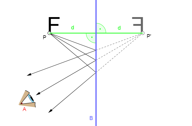
Taken from Wikimedia Commons
We’re going to dive into the image characteristics of plane mirrors by answering the following questions:
1. Where’s the image, and how does the height of it compare with the object’s?
2. Is the image real or virtual?
3. Is the image upright or inverted?
(1) Think back to when you look at yourself in a flat mirror; it seems as if the image of yourself is behind the mirror. When you take a step sideways, the image of you also steps sideways. The image seems as far behind the mirror as the object is in front of the mirror(the law of reflection can be used to show this). In a flat mirror, the image isn’t enlarged or shrunken compared to the size of the object.
(2) First off, what does it mean for an image to be real or virtual? An image is real if the light rays actually focus at the image; the light converges and passes through the actual image location. For flat mirrors, the image is virtual: light rays don’t actually pass through the image location on the other side of the mirror.
(3) Once again, re-imagine looking at yourself in a flat mirror. Your image isn’t upside down; it’s upright. Question 3 answered.
Check out this interactive to really solidify your understanding of plane mirrors.
Concave Mirrors & Convex Mirrors
Concave and convex mirrors are spherical mirrors, mirrors that are specifically curved so that their surfaces form part of a sphere.
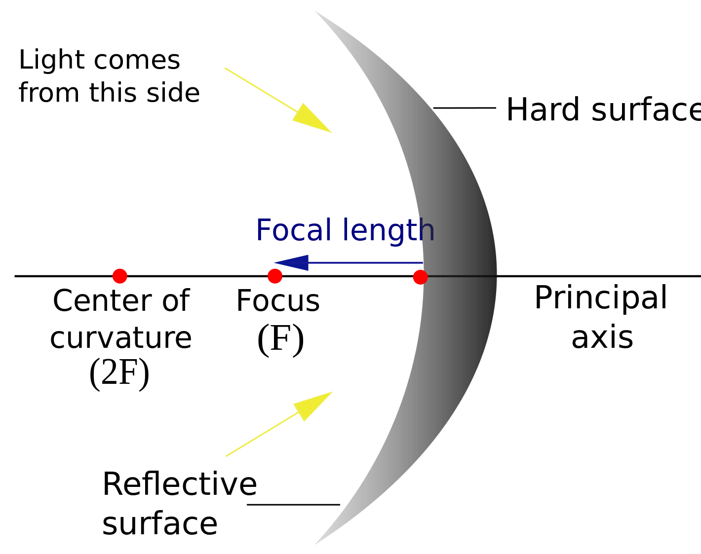
Taken from Wikimedia Commons
- Principal Axis—The line that passes through the center of the surface and the center of curvature of a spherical mirror.
- Center of Curvature (C)—The center of the imaginary sphere from which the section of the mirror was cut from.
- Radius of Curvature (R)—The radius of the imaginary sphere.
- Focal Point (Focus)—The point halfway between the center of curvature and mirror.
- Focal Length (f)—The distance from the mirror to the focal point.
- Vertex (V)—The intersection of the principal axis with the mirror; it’s also the geometric center of the mirror.
The focal length is one-half of the the radius of curvature:
f=R/2
The image above was a concave mirror; the reflective side is caved in towards the center of curvature. The following image is a convex mirror; the reflective side curves away from the center of curvature.
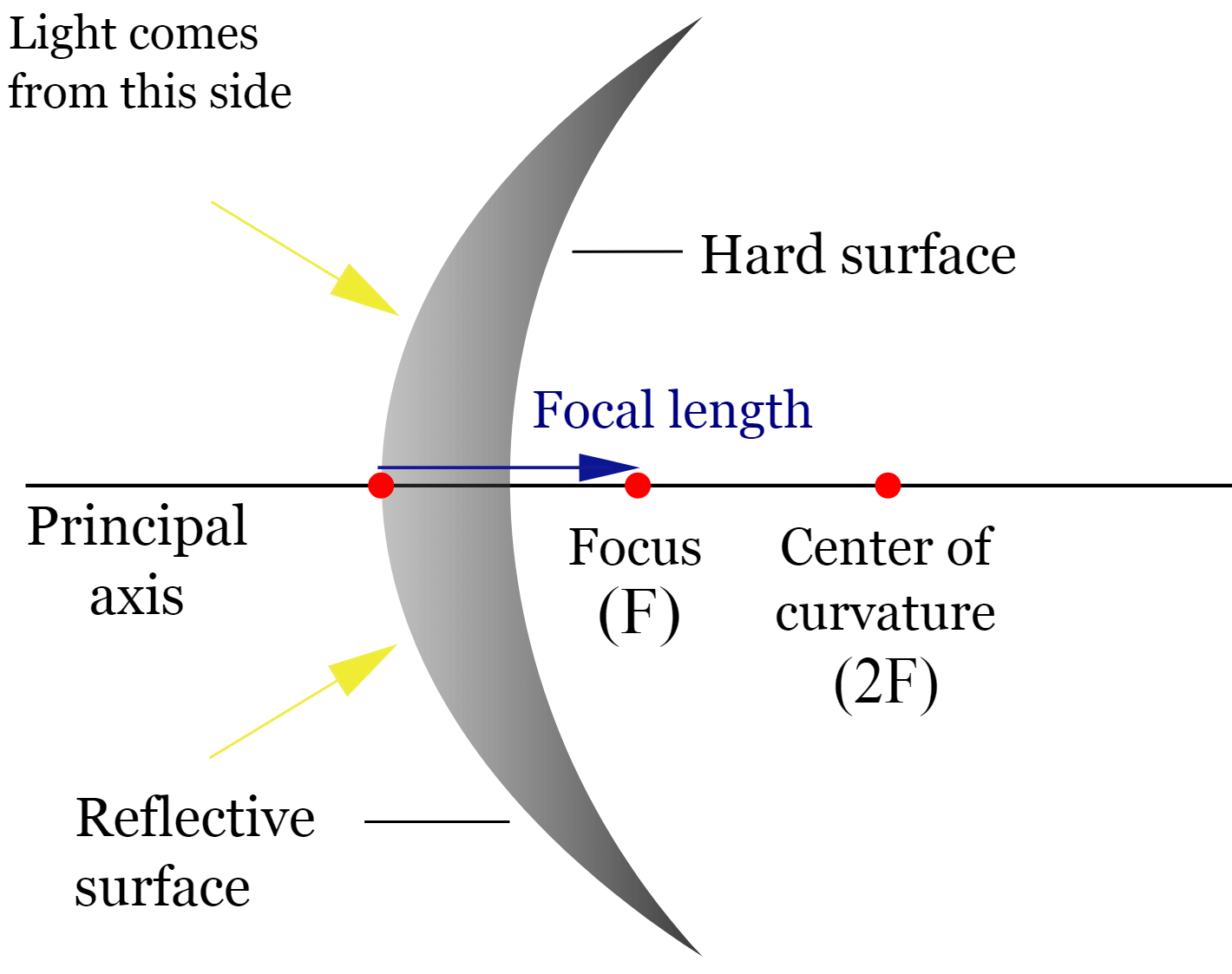
Taken from Wikimedia Commons
Ray Tracing for Mirrors
Ray tracing is an essential tool that helps us determine the location of the image. We draw representative light rays in a diagram along with the object and the mirror: the point at which the reflected rays intersect is the location of the image. Let’s go over some of the ray tracing rules:
Here are the steps for ray tracing for mirrors:
- Draw a diagram showing the position of the mirror and the location of the object.
- Draw two rays emanating from the top and bottom of the object and reflecting off the mirror.
- Predict the path of the rays after they reflect off the mirror using the laws of reflection.
- Determine the location of the image by finding the intersection of the two rays.
- Determine the size and orientation of the image by comparing the object and the image.
Concave Mirrors:
- An incident ray parallel to the principal axis is reflected through the focus.
- An incident ray that travels through the focus is reflected parallel to the principal axis.
- An incident ray that goes through the vertex is reflected at an equal angle to the principal axis.
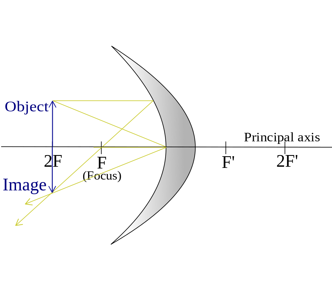
Taken from Wikimedia Commons
Convex Mirrors:
- An incident ray parallel to the principal axis is reflected in a way such that its extension passes through the focus.
- An incident ray that travels through the focus is reflected parallel to the principal axis.
- An incident ray that goes through the vertex is reflected at an equal angle to the principal axis.
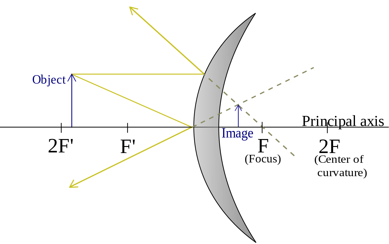
Taken from Wikimedia Commons
With ray tracing, if the image is on the same side of the mirror as the object, then the image is real; if it’s formed on the opposite side, it’s virtual. Other aspects of the image (its size, location, orientation) can be also determined by ray tracing. It might be a little tricky at first, but with practice, it'll get easier.
The Equations of Spherical Mirrors
To answer our questions about images in an easier and faster way, we can use two equations. The first is the mirror equation:
1/f=1/d_o+1/d_i
- d_o: the object’s distance from the mirror
- d_i: the image’s distance from the mirror
To differentiate mathematically between concave and convex, we set the focal length to the following:
- For concave mirrors, f is positive value
- For convex mirrors, f is negative value
The second equation is the magnification equation:
M=-d_i/d_o=h_i/h_o
h_i: height of image
h_o: height of object
- If d_i positive, then M is positive: the image is upright.
- If d_i negative, then M is negative: the image is inverted.
- If M<1, the image is reduced.
- If M>1, the image is enlarged.
- If M=1, the image is the same size as the object.
Keep in mind that all real images are inverted and all virtual images are upright.
Converging Lenses & Diverging Lenses
Lenses are optical devices that form images by refracting light. There are 2 types of lenses: converging and diverging.
Converging (convex) lens—converges parallel light rays to a focal point on the far side.
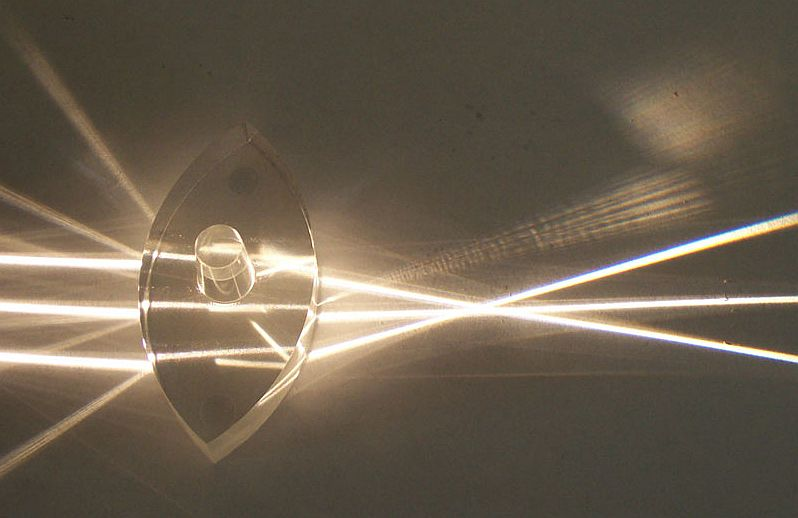
Taken from Wikimedia Commons
Diverging (concave) lens—causes light rays to diverge away from a focal point on the same side as the incident rays.
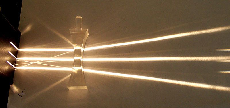
Taken from Wikimedia Commons
Ray Tracing for Lenses
Just as we did with mirrors, we can use ray tracing with lenses to get information about an image. Let’s go over the rules for ray tracing for lenses:
Here are the steps for ray tracing for lenses:
- Draw a diagram showing the position of the lens and the location of the object.
- Draw three rays emanating from the top, middle, and bottom of the object.
- Draw the first ray parallel to the optical axis and predict its path after it passes through the lens using the lens equation.
- Draw the second ray through the center of the lens and predict its path after it passes through the lens using the lens equation.
- Draw the third ray through the focal point of the lens and predict its path after it passes through the lens using the lens equation.
- Determine the location of the image by finding the intersection of the three rays.
- Determine the size and orientation of the image by comparing the object and the image.
Convex Lenses:
- An incident ray traveling parallel to the principal axis is refracted through the focus.
- An incident ray passing through the focus refracts through the lens and travels parallel to the principal axis.
- Incident rays that travel through the center point of the lens pass undeflected.
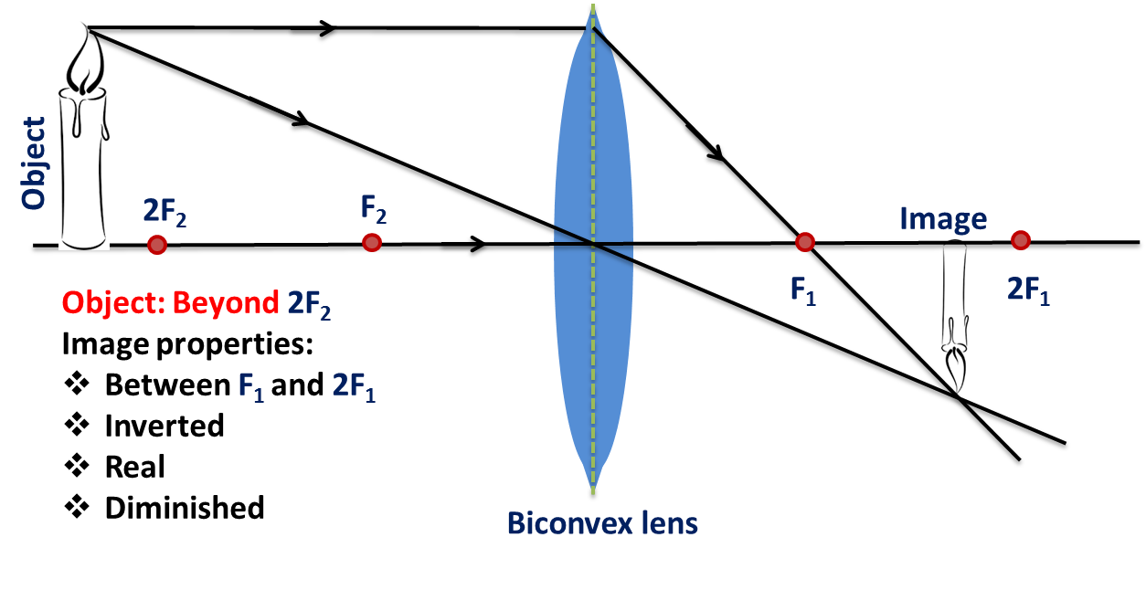
Taken from Wikimedia Commons
Concave Lenses:
- An incident ray traveling parallel to the axis refracts through the lens and travels in line with the focal point.
- An incident ray passing through the focal point refracts through the lens and travels parallel to the principal axis.
- Incident rays that travel through the center point of the lens pass undeflected.
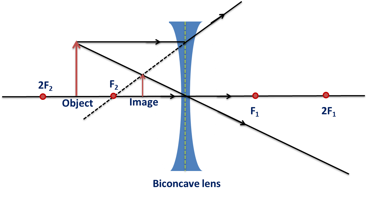
Taken from Wikimedia Commons
The Equations of Lenses
Lens and mirrors use the same equations! Just keep in mind that:
- Converging optical devices(+f): concave mirrors and convex lenses
- Diverging optical devices(-f): convex mirrors and concave lenses
Some simulations to check out for lenses and mirrors:
Practice Problems🧩
1. A plane mirror produces an image that is:
A) real, inverted, and larger than the object.
B) real, upright, and the same size of the object.
C) real, upright, and smaller than the object.
D) virtual, inverted, and smaller than the object.
E) virtual, upright, and the same size as the object.
2. An object is located 0.20 meters from a converging lens which has a focal length of 0.15 meters. Relative to the object, the image formed by the lens will be:
B) real, inverted, smaller
C) real, inverted, larger
D) virtual, erect, larger
E) virtual, inverted, smaller
3. A narrow beam of monochromatic light enters a lens parallel to the optic axis, as shown in the accompanying diagram. Which arrow best represents the direction of the light after leaving the
lens?
B) B
C) C
D) D
E) E
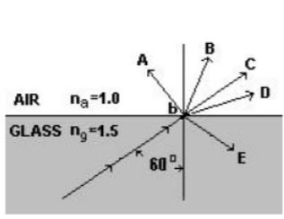
4. A beam of light traveling in glass (n_gng = 1.5) strikes a boundary with air (n_ana = 1.0) at point P. The angle of incidence is 60° as shown in the diagram. Which ray would best indicate the beam’s path after point P?
A) A
B) B
C) C
D) D
E) E
5. An object is placed 10 cm in front of the center of a concave curved mirror with a radius of curvature of 10 cm. About how far from the mirror will the real image of the object be formed?
A) 0 cm
B) 5 cm
C) 10 cm
D) 20 cm
E) No image is formed
6. A diverging lens produces an image of a real object. This image is
A) virtual, larger than the object, and upright
B) virtual, smaller than the object, and upright
C) virtual, smaller than the object, and inverted
D) real, smaller than the object, and inverted
7. An illuminated object is placed 0.30 meter from a lens whose focal length is –0.15 meter. The image is
B) upright, virtual, and 0.30 meter from the lens on the opposite side from the object
C) upright, real, and 0.10 meter from the lens on the same side as the object
D) upright, virtual, and 0.10 meter from the lens on the same side as the object
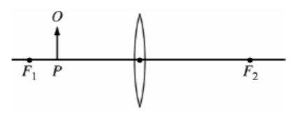
Use the Figure above for questions 8 and 9. An object O is located at point P to the left of a converging lens, as shown in the figure. F_1F1 and F_2F2 are the focal points of the lens.
8. If the focal length of the lens is 0.40 m and point P is 0.30 m to the left of the lens, where is the image of the object located?
A) 1.2 m to the left of the lens
B) 0.17 m to the left of the lens
C) At the lens
D) 0.17 m to the right of the lens
E) 1.2 m to the right of the lens
9. Which of the following characterizes the image when the object is in the position shown?
A) Real, inverted, and smaller than the object
B) Real, upright, and larger than the object
C) Real, inverted, and larger than the object
D) Virtual, upright, and larger than the object
E) Virtual, upright, and smaller than the object
10. A physics student places an object 6.0 cm from a converging lens of focal length 9.0 cm. What is the magnitude of the magnification of the image produced?
A) 0.6
B) 1.5
C) 2.0
D) 3.0
E) 3.6
Answers:
- E: Plane mirrors always makes virtual, same size, upright images
- C: Using the math, 1/f = 1/do + 1/di, and M = – di / do … di +0.6 M = – 3 …
- E: A horizontal beam approaching a converging lens bends and converges through the focal point
- E: Generally when we go from more–less we should always check the critical angle first rather than assuming the ray will refract and bend away. Choice D might be correct, but not until we first check the critical angle for total internal reflection. Use ni sin θc = nr sin (90), ni=1.5, nr=1θc = 41.8°. Since our incoming angle (60) is larger than the critical angle, total internal reflection will occur and you will get choice E.
- C: The focal point is = R/2. Then use the math 1/f = 1/do + 1/di … and di = 10
- E: Fact about diverging lens.
- D: Using the math, 1/f = 1/do + 1/di, and M = – di / do … di = – 0.10 m, M = +0.33
- A: Using the math, 1/f = 1/do + 1/di, di = –1.2. Its virtual so its on the same side as the object, which puts the image on the left side of the lens
- D: This is a magnifying glass, which can be memorized or the math can be done to prove the answer
- D: Using the math, 1/f = 1/do + 1/di, di = –18 … then M = – di / do … M = 3
Browse Study Guides By Unit
💧Unit 1 – Fluids
🔥Unit 2 – Thermodynamics
⚡️Unit 3 – Electric Force, Field, & Potential
💡Unit 4 – Electric Circuits
🧲Unit 5 – Magnetism & Electromagnetic Induction
🔍Unit 6 – Geometric & Physical Optics
⚛️Unit 7 – Quantum, Atomic, & Nuclear Physics
📆Big Reviews: Finals & Exam Prep
📚Study Tools

Fiveable
Resources
© 2025 Fiveable Inc. All rights reserved.