Peter Apps
AP Physics C: E&M 💡
26 resourcesSee Units
After looking back at 20+ years of FRQs, if you see an FRQ on circuits, there's a really good chance it will have a capacitor in it. You've been warned 🙂
Capacitors in Series & Parallel
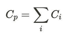
Capacitors have their own special equations for determining equivalent resistance in series or parallel, just like resistors.
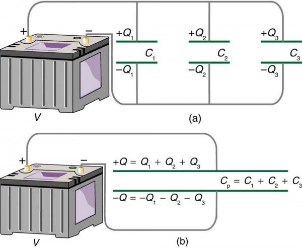
Image from lumenlearning.
com
For a parallel circuit, individual capacitors act as one large capacitor storing a large charge (Q_{total} = Q_1 + Q_2 +Q_3) resulting in a total capacitance that is simply the sum of the individual values.
A series circuit is a bit trickier since the charge is split up along each of the capacitors, but we can derive an expression for this by using the KVL (sum of voltage drops needs to be equal to the battery voltage)
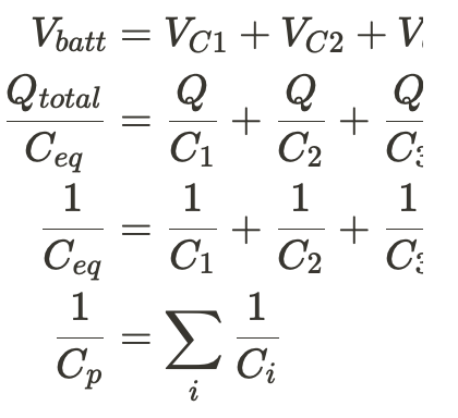
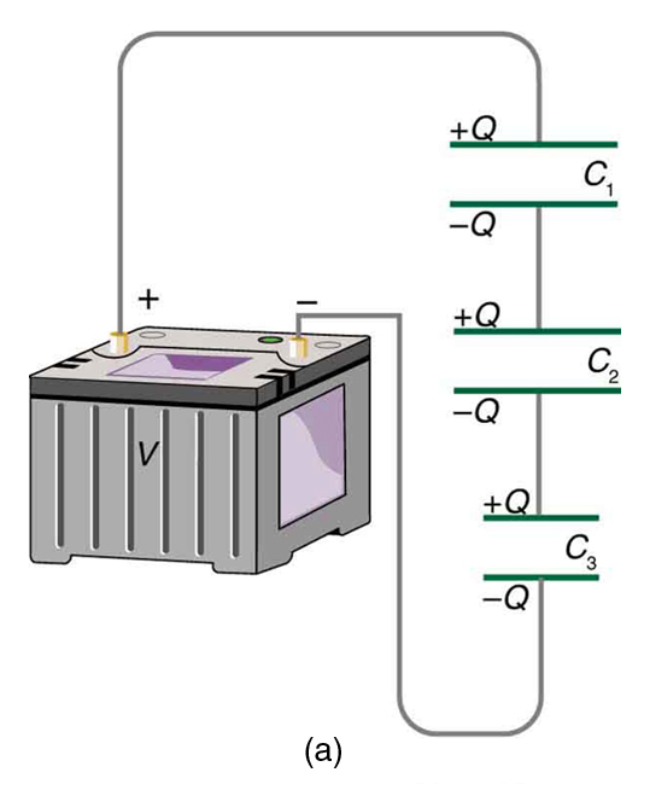
image from lumenlearning.
com
Steady State Behavior 🎯
In a DC circuit, an initially uncharged capacitor will begin storing charge on its plates, increasing its potential difference until the voltage of the capacitor is equal to the voltage of the battery or other supply source. At this point, there is no current passing through the capacitor and it acts as an open switch or a break in the wire.
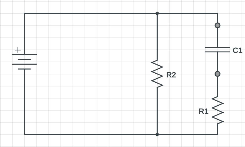
For example, in the circuit below, the current initially flows through both branches, but as the voltage of C1 approaches the battery voltage, less and less current passes through R1. When steady state is reached, the circuit will appear to be a series circuit with only R2 in it.
RC Circuits 🏍️
The RC circuit is a very common type of capacitor where a resistor and capacitor are connected in series with each other. A switch is used to allow the capacitor to charge (position a) or discharge (position b).
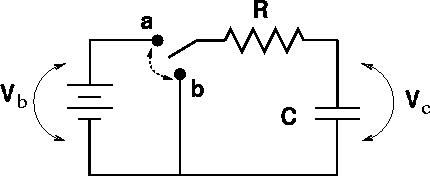
Image from web.pa.msu.edu
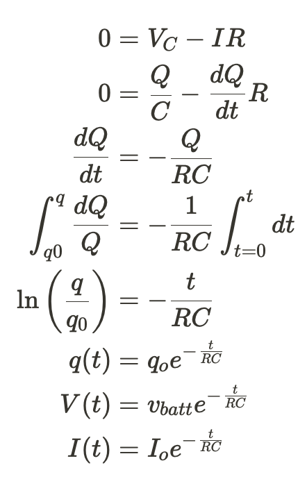
The cool thing about RC circuits is that the charging and discharging time can be tweaked by changing the values of C and R. Let's derive a few useful equations for this circuit.
- Charging the Capacitor
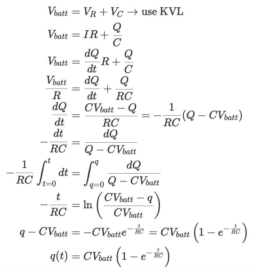 I know that's a lot of math, but we've just derived an equation for the charge on the capacitor as a function of time! We can also tweak this equation to get derivations for V(t) and I(t) as well.
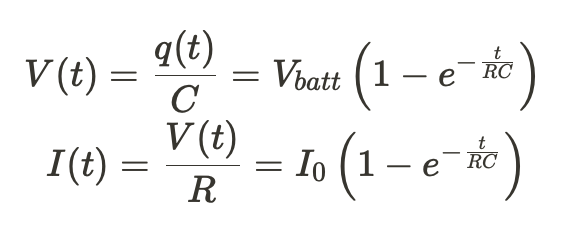 Graphing these functions shows us the changes in V and I as the capacitor charges. Notice how when the steady-state is reached, the current in the capacitor is basically zero.
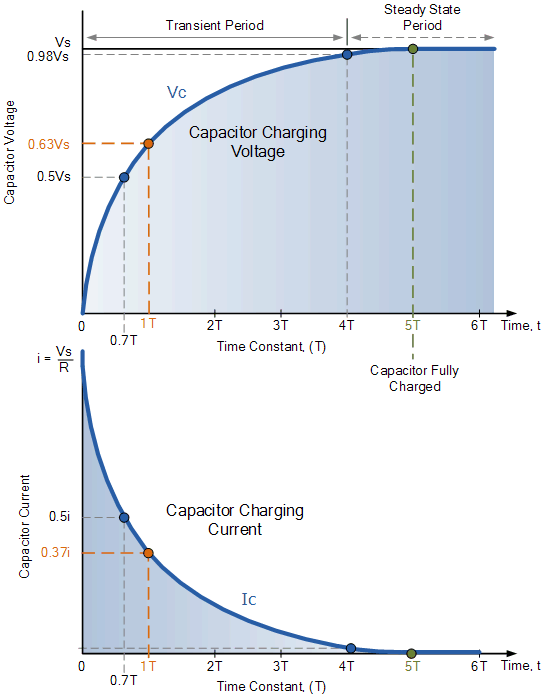
Image from electronics-tutorials.ws
- Discharging the CapacitorWe're going to follow the same process we did with generating the charging equations.
 Now we can make the same sort of graphs as we did for the charging segment.
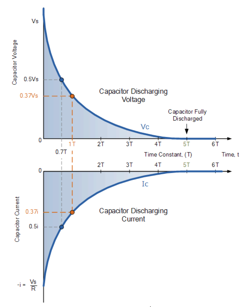
Image from electronics-tutorials.ws/
In all these cases notice how $\frac{1}{RC}$ shows up in the exponential. This is called the time constant for the RC circuit and determines the exact time it will take for a capacitor to reach steady-state or to discharge from steady-state back to 0 V. Because of this tuneable feature, RC circuits are frequently used in electronics projects as low-pass or high-pass filters to remove noise from audio signals.
Practice Questions
1)
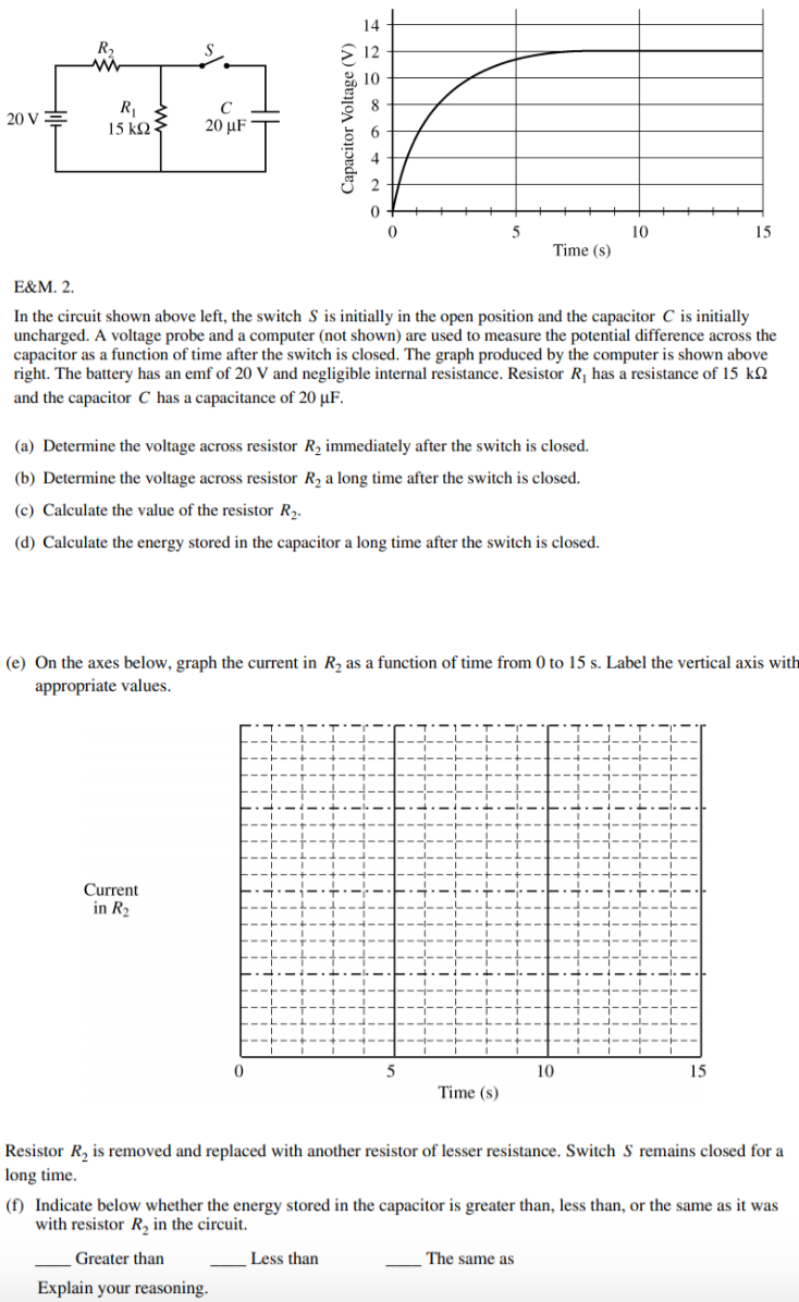
Image from collegeboard.org
Answer
a) Because R_1 is in parallel with C their voltage drops must be equal at any given time. At t=0, V_C = 0 on the graph, so the voltage on R_2 must be equal to the battery's EMF which is 20V.
b) Similar logic as in part (a). V_c = R_1= 12V at the steady state region and we know that ε = V_1 + V_2$ so the voltage on R_2 must be 8V
c) In the steady state region no current passes through the capacitor, so we can consider the entire circuit as a series circuit with R_1 and R_2 connected to the battery. Using Ohm's Law we can calculate the current flowing through R_1 which must be the same as the current flowing through R_2. Using that value with our known V_2 from part (b) lets us get the answer.
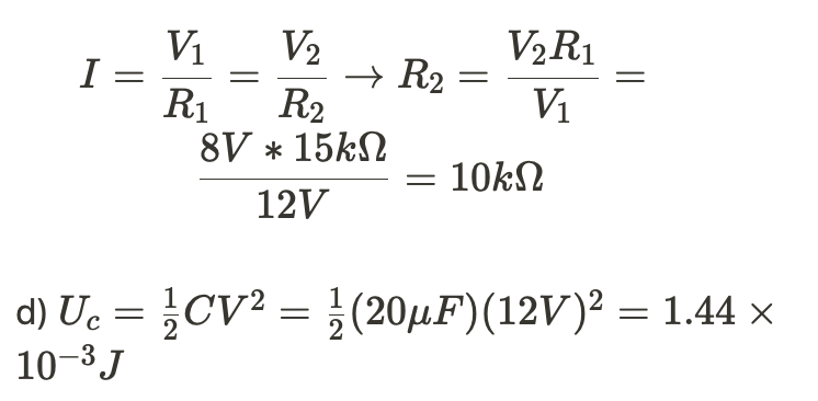
e) Initial conditions:

steady state:

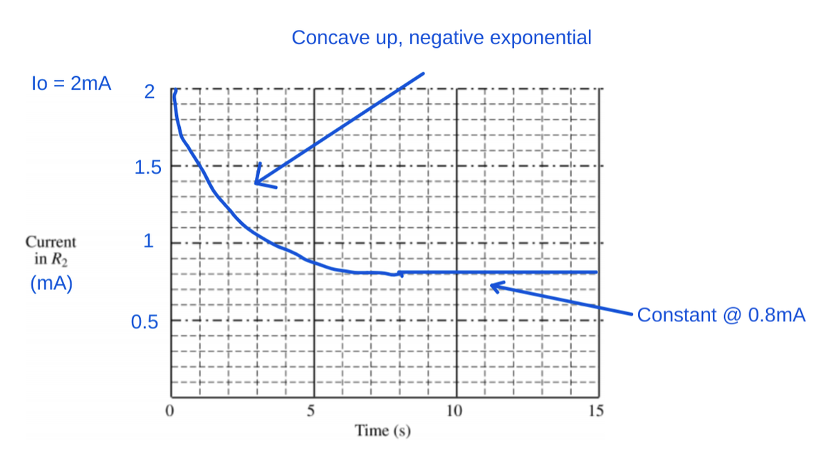
image created by author
f) The energy stored in the capacitor will increase. The energy stored depends on the voltage of the capacitor and it's capacitance. V_c and V_{R_1}must be equal to each other because they are connected in parallel. Therefore anything that increases the voltage across R_1will result in more energy stored in the capacitor. By decreasing R_2 (and keeping everything else the same), that allows more current to flow through the circuit (because in the circuit R_{eq} = R_1 + R_2 and resistance is inversely proportional to the total current). According to Ohm's Law, increasing the current in a resistor will increase it's voltage drop (V=IR) so increasing the current makes a larger V_{R_1}which makes a larger V_C which means more energy stored in the capacitor (U_c = 1/2 CV^2)
2)
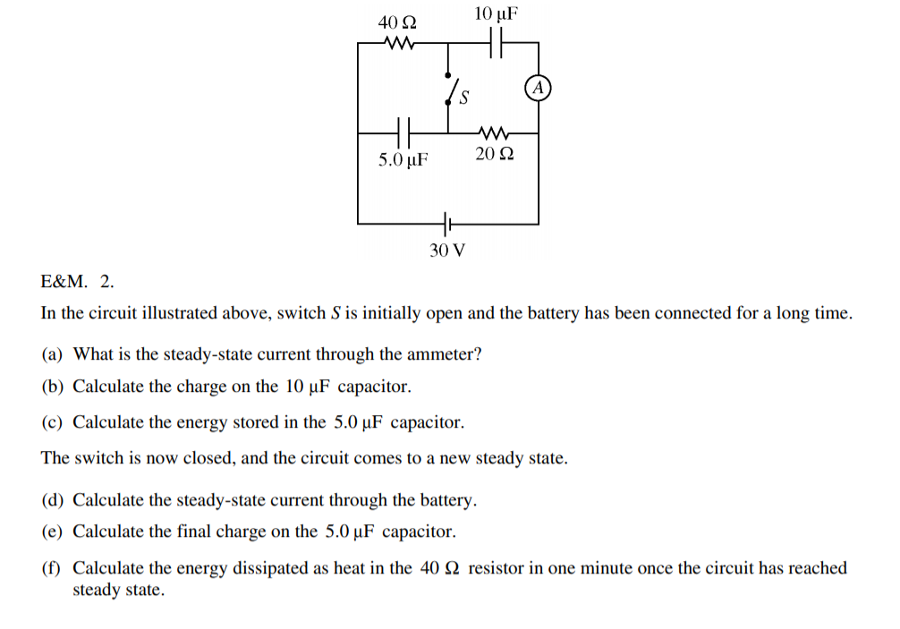
Image from collegeboard.org
Answers
a) With the switch open and all the capacitors acting like open switches as well ("connected for a long time"), there's no current flowing through the ammeter.
b) In a steady state configuration, the charged capacitor must have a voltage equal to the battery's so

c) Same logic as (b), the capacitor must have a voltage of 30V

d) With the switch closed, the steady state circuit can be simplified to a series circuit.

e)The 5μ F capacitor is in parallel with the 40Ω resistor, so their voltages must be the same


Browse Study Guides By Unit
⚡️Unit 1 – Electrostatics
🔋Unit 2 – Conductors, Capacitors, Dielectrics
🔌Unit 3 – Electric Circuits
🧲Unit 4 – Magnetic Fields
⚛️Unit 5 – Electromagnetism
📚Study Tools
📚Exam Skills

Fiveable
Resources
© 2025 Fiveable Inc. All rights reserved.