4.2 Current-Carrying Wires & Magnetic Fields 🧲
6 min read•january 13, 2023
Peter Apps
AP Physics C: E&M 💡
26 resourcesSee Units
In section 4.1, we looked at magnetic forces acting on individual charged particles. Now we'll take a look at the effect of an external magnetic field on a wire with current traveling through it.
Forces on a Wire in an External Magnetic Field ✅
This is very similar to the work we did in 4.1. The direction of the force will be found using the Right-Hand Rule, except instead of pointing your thumb in the direction of the velocity of the particle, you point it in the direction of the current in the wire. To calculate the magnitude of the force, we can derive the following equation starting from our work in 4.1.
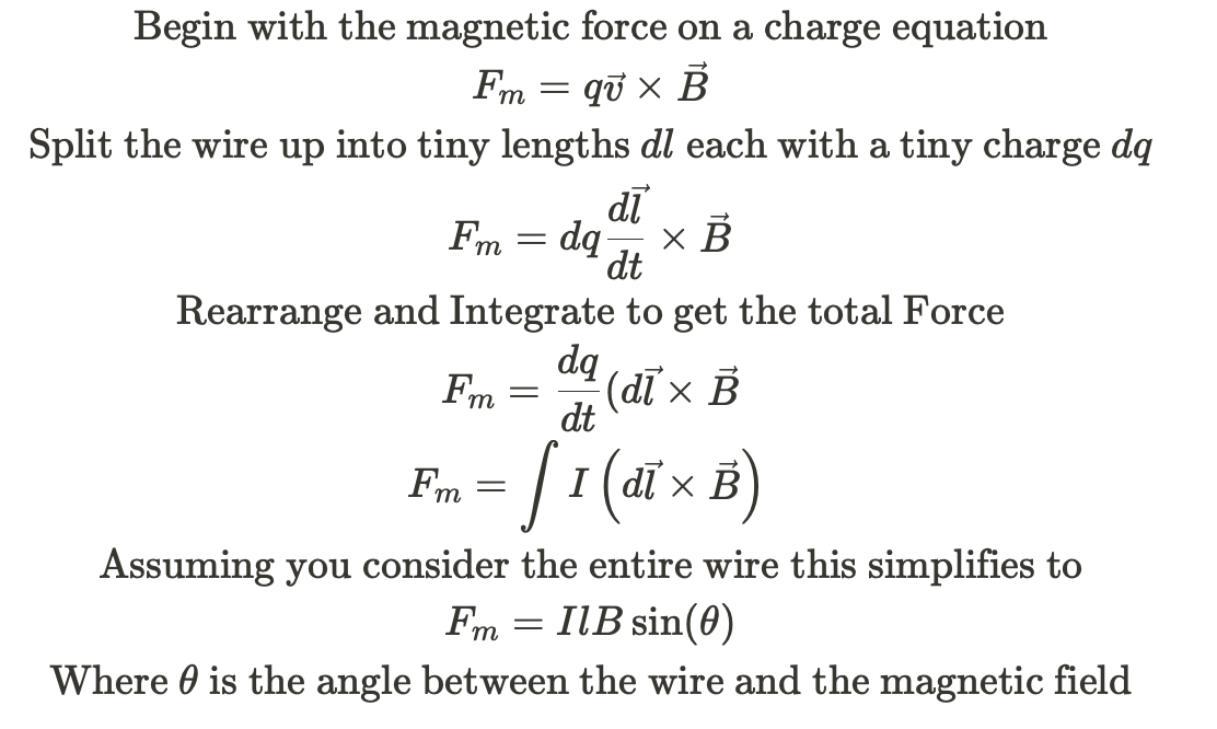
Let's apply this to an example below. Here, we look at 2 straight sections and 1 curved section of wire with a current applied to it, placed in a magnetic field that is directed into the page.
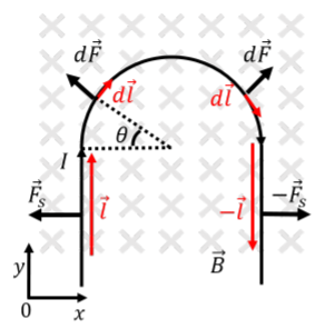
Image from phys.libretexts.org
In the straight sections, we can simply calculate vec{F_s} by considering the entire section. The angle between the length vector and the magnetic field is 90, so this simplifies to F_s = IlB. The direction will depend on if our length vector is pointing in the + or - y-direction.
On the curved section, we need to break this up into dl partitions, each getting a small force, dF. However, we can save ourselves a bit of work by noticing that, because the curve is symmetrical in the x-direction, the net horizontal force will cancel out. So we only need to do the math for the y-direction.
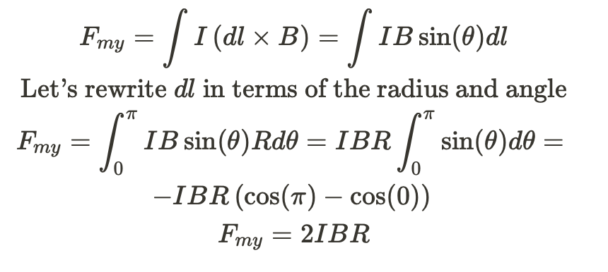
In the example above, we were able to ignore the x components because of symmetry. If the curved section became a solid loop, we'd be able to say that the x and y components would cancel out. Thus in a closed loop of wire with a current flowing through it, the magnetic field is 0.
Torque on a Wire 🚨
Even though a loop of wire has no net magnetic force, it's possible that it will still have a net torque.( If you'd like a quick review of torque, check out this Fiveable Study Guide) Let's look at an example to see how this occurs.
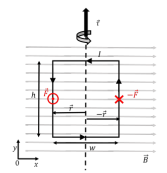
Image From phys.libretexts.org
Here we have a closed loop of wire with a current, I, flowing in it. Using the right-hand rule, we can see that the magnetic force is coming out of the page on the left side of the loop and going into the page on the right side of the loop. For convenience sake, we're going to define our axis of rotation the exact center of the loop and the force vector as coming out of the page is in the positive z-direction.

So, because the force vector and the radius are both pointing in their respective negative directions on the right side of the loop, this results in a positive torque for both sides of the loop and it will start rotating! This is one of the fundamental concepts that make electric motors work.
Magnetic Fields From a Current Carrying Wire 🌐
We've seen that a current-carrying wire can be affected by external magnetic fields. This is only possible if the current-carrying wire has its own magnetic field.
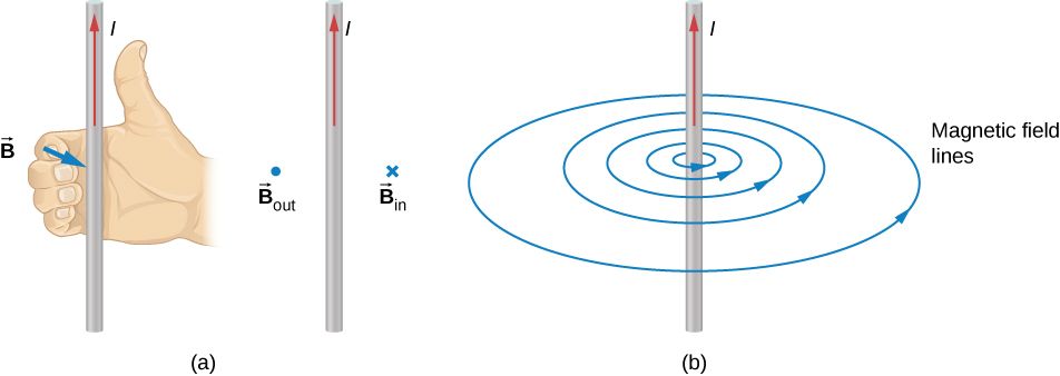
Image from cnx.org/
Any wire with current passing through it becomes an electromagnet. The magnetic field lines are circular around the wire radiating outwards. Again, we can use the right-hand rule to determine the direction of the magnetic field. This application will be referred to as the Right-Hand Curl Rule (RHCR) since we now have 3 applications of this rule.
To do the RHCR, you position your hand with your thumb pointing in the direction of the current and curl your fingers around the wire. Your fingers point in the direction of the magnetic field. In the example above, the B field is coming out of the page to the left of the wire and going into the page on the right side of the wire.
The internal magnetic field created by a very long current-carrying wire can be determined using the equation:
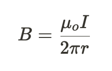
I is the current flowing through the wire, μ_o is the permeability of free space constant (found on the front page of your reference tables), and r is the distance away from the wire.
At this point, we're just going to use this equation. In section 4.3, we'll cover where it comes from and how to derive it.
Forces Between Two Wires 🧲
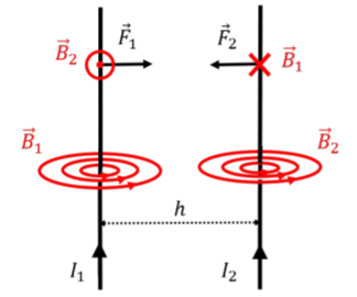
Image from phys.libretexts.org
Let's look at what happens when we place 2 current-carrying wires close together. We can see that both wires create magnetic fields. Wire 2 is affected by the magnetic field from Wire 1 and vice versa. Using the right-hand curl rule, we can see that B_1 is going into the page at Wire 2's location. Using the right-hand rule (no curl), we can determine that this field creates a force on Wire 2 directed to the left.
Likewise, B_2 coming out of the page at Wire 1's location creates a force pushing Wire 1 to the right. These two wires are attracted to each other because of their magnetic fields. This occurs because the currents are parallel to each other. If we switched the current in either of the wires so they are running anti-parallel, then the forces would cause the wires to repel.
For a more detailed explanation of how this phenomenon works, check out part 2 of the Minute Physics video series on magnets.
Here are some key things to remember when drawing a magnetic field:
- A magnetic field is a region around a magnet or electric current where the force of magnetism can be detected.
- The direction of the magnetic field at a particular point is the direction that a north pole of a magnet would point if it were placed at that point.
- The strength of the magnetic field at a particular point is related to the density of the field lines at that point. Field lines that are closer together indicate a stronger magnetic field.
- The magnetic field lines around a magnet form closed loops, with the direction of the field given by the right-hand rule.
- The magnetic field lines around a current-carrying wire form concentric circles around the wire, with the direction of the field given by the right-hand rule.
- When drawing a magnetic field, it is important to pay attention to the direction of the field lines and the strength of the field at different points.
- You can use a magnetic field viewer (such as iron filings or a piece of paper with a magnet placed under it) to visualize the shape and direction of the magnetic field.
Practice Questions

Image from apclassroom.collegeboard.org
1. The circuit shown above consists of a battery of emf ε in series with a rod of length l , mass m, and resistance r. The rod is suspended by vertical connecting wires of length d, and the horizontal wires that connect to the battery are fixed. All these wires have negligible mass and resistance. The rod is a distance r above a conducting cable. The cable is very long and is located directly below and parallel to the rod. Earth’s gravitational pull is toward the bottom of the page. Express all algebraic answers in terms of the given quantities and fundamental constants.
a) What is the magnitude and direction of the current l in the rod?
b) In which direction must there be a current in the cable to exert an upward force on the rod? Justify your answer.
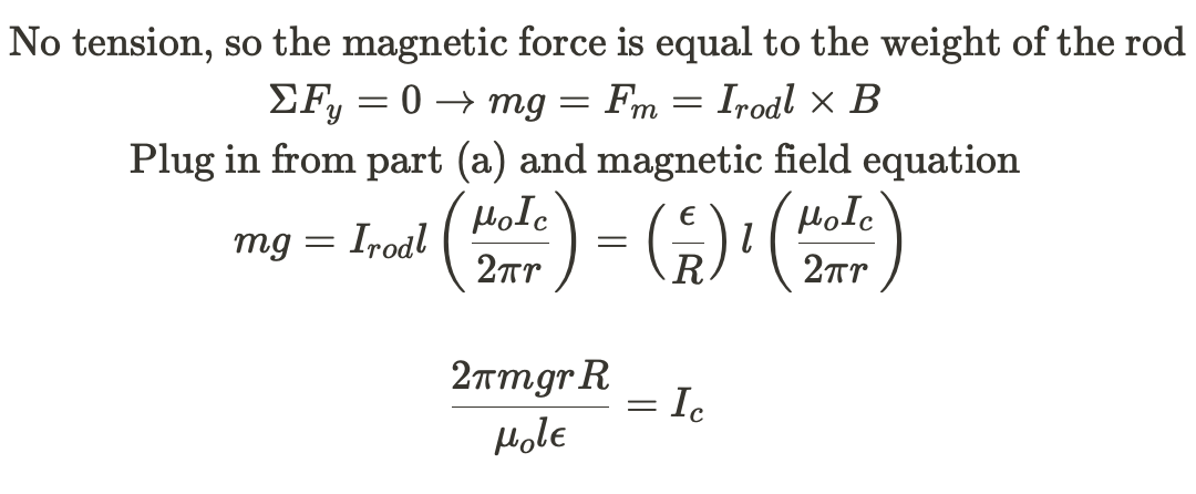
c) With the proper current in the cable, the rod can be lifted up such that there is no tension in the connecting wires. Determine the minimum current l_c in the cable that satisfies this situation.
Answers
a)

Conventional current leaves the + terminal and travels to the - terminal (CCW in this diagram), so the current in the rod is directed to the left.
b) Because the current in the rod is directed to the left, it will create a magnetic field coming out of the page between the rod and the cable (Right Hand Curl Rule). To lift the rod upwards the cable must create a magnetic field that will repel it, which means that the current in the cable must me traveling to the right (RHCR).
c)
Browse Study Guides By Unit
⚡️Unit 1 – Electrostatics
🔋Unit 2 – Conductors, Capacitors, Dielectrics
🔌Unit 3 – Electric Circuits
🧲Unit 4 – Magnetic Fields
⚛️Unit 5 – Electromagnetism
✍️Exam Skills- FRQ/MCQ
🙏Exam Reviews

Fiveable
Resources
© 2023 Fiveable Inc. All rights reserved.